Ideas
Your First 3D Modeling Project: A Cable Name Tag for Your Desk
Start with a paper footprint, build a simple plate and attachment hole, and review the model before printing. One useful desk decision at a time.
By Hobby-ist Editorial Team · 6 min read · October 6, 2026
In this story
Your first 3D model can solve a very small desk problem: telling two similar cables apart. Instead of starting with a tight snap-on clip, make a flat name tag with a hole for a loose soft tie. You can learn dimensions, placement, subtraction and checking a model without first making a part that must grip a cable.
Why we picked it: this project connects a digital shape to a decision you can measure on your own desk. It also gives you an honest stopping point: an editable model and a review record, even if you do not have access to a printer. The dimensions below are Hobby-ist's exercise proposal, not a tested product specification.
Decide whether you need a model or just a label
If your only aim is to identify a cable today, a paper flag or a suitable ready-made label is the quicker option. A rigid printed tag takes space, can swing around, and becomes inconvenient when the cable passes through a narrow opening. Choose this project if you want to learn modeling as well as labeling, and have room for a small tag near an accessible cable end.
This is an identification accessory for an ordinary desk cable, not a cable clamp, repair, strain relief, or electrical safety component. Keep the tie loose, avoid sharp contact and tight bends, and leave connectors, ventilation and device controls unobstructed. Do not use an improvised tag where heat, moving equipment or a special cable system creates different requirements. A paper label may be the better outcome.
If you want to try modeling before buying equipment, our renting versus buying guide gives a useful way to separate learning interest from ownership. This article does not assume a local printing service has availability, or that borrowing a printer includes permission to operate it.
Measure the placement before opening the editor
Write down three decisions: the short name you need to read, the space where the tag will sit, and the attachment you intend to use. Choose one word or code such as “USB” or “MIC” before designing a long device name. Avoid putting an account name or other personal detail on a visible tag.
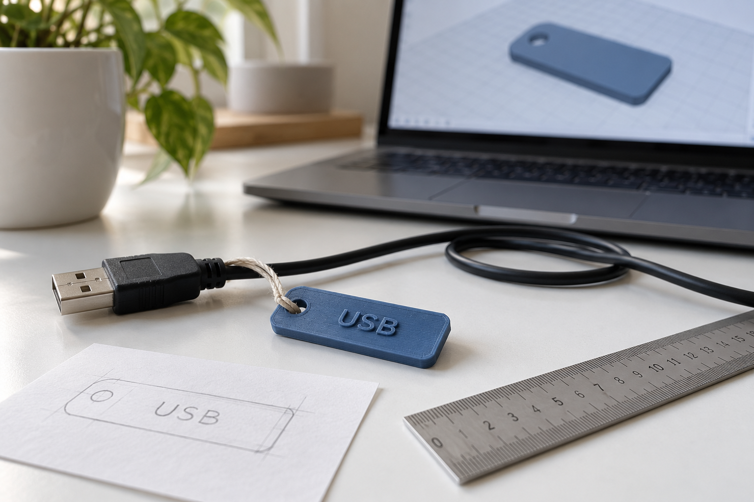
Cut a paper rectangle and place it beside the intended cable position. Can you read the name from your usual seat? Does the shape collide with a neighboring connector or become annoying when the cable moves? This checks the footprint, not the strength or fit of a future print. Adjust the paper size before treating screen proportions as real-world size.
For a starting exercise, try a 40 mm long, 16 mm wide plate, 3 mm thick, with a 4 mm diameter attachment hole. These numbers are a suggested model to revise. They do not guarantee that your tie, printing process, or desk will suit the result. The hole is for the tie; you are not threading a connector through it or matching the cable diameter.
Build a plate and an attachment hole
Use an editor that lets you enter dimensions, combine solids and subtract a hole shape. Tinkercad is one option; its official learning area is a starting point if navigating a 3D view is new. Complete a basic movement and sizing exercise before adding details. Tool locations can change, so use the named functions in your current editor.
Create the plate with its bottom on the workplane and confirm the units and all three dimensions. View it from above and from the side. A rectangle that looks sensible from above might still be far too tall. Keep a plain version before rounding edges or adding decorative geometry.
For the suggested 40 × 16 mm plate, put the hole center 6 mm from a short end and halfway across the 16 mm width. A 4 mm hole then leaves 4 mm between its nearest edge and that short end. This is a geometric check, not a claim about strength. Make the cutting cylinder extend completely through the thickness, select it and the plate, and subtract it. In Tinkercad, a Hole shape grouped with a solid makes that cut. The University of Warwick's basic instructions explain Hole, Group, Align and placing shapes on a face.
Add a short readable name
Place simple solid text on the top face, away from the hole and plate edges. If your editor offers a workplane on a face, use it to position the text, then inspect the side view. Ensure the letters connect to the plate rather than float above it. Combine them into the final solid and inspect the result again.
You can start by aiming for about 0.8 mm of raised lettering, with its base slightly overlapping the plate before combining. That is another proposed exercise value, not a universal printing setting. A very small font or thin strokes may disappear or become hard to read. Make the word shorter or larger before introducing multiple colors. Screen colors do not guarantee that a print will contain those colors.
For this first version, raised text is easier to inspect than deep engraved lettering that might leave too little plate below it. Neither approach is automatically printable. Save a separate editable version before combining objects so you can change the word without rebuilding the whole tag.
Review the model before considering output
Check the overall dimensions, hole diameter and location, the text-to-plate connection, and the flat underside. Look from more than one angle. A convincing screenshot does not prove the hole is open or the letters are attached. Name versions with the changed feature, such as “tag-v2-larger-text,” and record why you changed it.
If printing is available, export the required model format and have it reviewed with the intended printer, material and profile. In the slicer, confirm the displayed dimensions rather than assuming the import scale is correct. Inspect the layer preview for the open hole, continuous plate and actual letter paths. An STL model is an intermediate file, not printer-specific operating instructions.
Prusa's official modeling guide explains that small features and tolerances depend on the printing setup and that test prints are part of refining a design. That is why we do not specify a universal clearance or promise the proposed text will print on every machine. Ask the operator to review the model and the attachment hole before committing to a batch.
Make one test, or finish with a digital review
If you print, start with one tag. Before putting it on a cable, check for rough edges, readable lettering, and a tie that passes through freely. Reject or revise a result that creates sharp contact, pinches the cable, or interferes with its use. Then assess its position on the desk and whether the rigid tag is actually more useful than the paper prototype. A finished print can still be the wrong choice.
If you do not print, keep the editable model, an export if needed, a few views, and a measurement note. Record what a physical test must still establish. That is a completed modeling exercise, with physical fit and durability left unverified. Do not present a rendered image as proof of a successful print.
Before spending, include a trial print and possible revisions in your hobby budget. If the obstacle is understanding the view or combining shapes, our self-study versus class guide can help you choose support before new hardware.
Hobby-ist's final judgment
Model one label whose size you can explain, then decide whether it deserves to become an object. The most useful first lesson is connecting a dimension to a real desk decision. A revised digital tag or a decision to keep the paper label can both show that you learned something. Make a set only after one physical sample proves useful.
Editorial status: Researched. We consulted modeling guidance and educational instructions. The layout, dimensions and review sequence are Hobby-ist's proposed exercise; the team did not build, print or fit-test this tag. The AI cover illustrates the concept and is not a photograph of a verified prototype.
Sources & verification
Information checked: 2026-10-06